Sunday, December 28, 2014

Debugger for Arduino (Visual Micro)

Visual Micro is very an interesting extension for Microsoft Visual Studio (it works also in Atmel Studio). It allows you to program Arduino directly from Visual Studio environment – that’s cool, but that’s not all!

Visual Studio is incomparable with Arduino IDE in terms of users experience. It gives you all kinds of goodies like IntelliSense, syntax highliting, code navigation, git/svn/whatever integration and so on. But wait for it… it gives you also a debugger!

Debugging AVR processor requires dedicated external HW debugger, which is pretty expensive gadget. So Visual Micro is not true debugger but still, fairly awesome.

How it works?

Visual Micro utilize technique called Instrumentation.

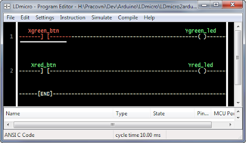
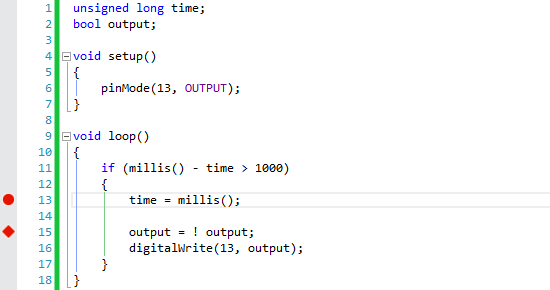
We can take this code as an example:

When you start debugging in VS, Visual Micro takes your code and inserts small pieces of its own code into it. First is at the beginig of setup() and next to everywhere where breakpoints are.

Result is saved to temporary folder, so anybody can look at it. Path to it is usually something like c:\Users\{UserName}\AppData\Local\VMicro\Arduino\Builds\

Result of this process for the example shown above looks like this:

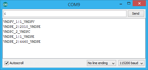
If you open it in normal Arduino IDE, Serial Monitor gives you something like this:

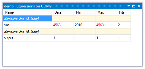
The magic happens when Visual Micro takes this cryptical lines and visualize it nicely in Visual Studio.

And that’s what you are paying for. Visual Micro with Debugger is not for free. The instrumentation is fairly simple, but the integration into Visual Studio is more difficult part. Price starts at $29. But it’s worth it.

Friday, September 27, 2013

Arduino Yún Naked

The “linux” part of Arduino Yún is mostly hidden under shielding. I was wondering what’s under it. Luckily shielding is mounted only by two solder joins. So nothing that soldering iron and soldering wick can't handle…

If you read the documentation it’s nothing surprising. On the following photo there is also description of the main parts.

More photos…

Note: The connector for external Wi-Fi antenna looks like U.FL but it’s NOT! Actually it’s SWF connector. Unfortunately purpose of this connector is mainly during product testing, so counterpart is far less available than U.FL connector.

Sunday, July 17, 2011

LDmicro and Arduino

Ladder Logic for Arduino.

In this article the way how to run program in ladder logic from LDmicro on Arduino is presented. LDmicro is free SW to write and simulate ladder logic programs. When is ladder logic program is successfully simulated it could be compiled for AVR or PIC processor. However ATmega used in Arduino is not supported. Fortunately LDmicro can “compile” code into ANSI C. So, let’s take a look how we can run this code on Arduino.

Little Background

When we select ANSI C Code as Microcontroler type in Settings menu of LDmicro after compile we will get C file. This file contains all logic but it requires header file ladder.h which is missing. So, we have to implement this file. Let say we have input contact called “button” then we have to implement function:

BOOL Read_U_b_Xbutton(void) {
 return digitalRead(10); // button on digital pin 10
}

And similar to others input and output pins. Actually we have to write the layer between leader logic program and real HW of Arduino. And it could be more than simple call of digitalRead or digitalWrite. For example we could control servos, read data from proximity sensor and so on. Ability to write this layer is very powerful. Ladder logic could be used for core logic of application and C only for HW layer.

For more information read actual generated C file. It contains more information.

Generating ladder.h

If we need just direct control of digital IO pins of Arduino ladder.h could be easily generated for us. I wrote PHP script that can do this job. It requires generated code and mapping between variable name we use in ladder logic and pin numbers of Arduino. It will generate ladder.h with all nessesary functions and setup function (correctly calls pinMode for all used digital pin). Script could be used as console application or it’s also available online.

Step by step

Let’s do it step by step. Complete example is available for download.

1. Write code in LDmicro.

2. Select as Microcontroller “ANSI C Code”.

3. Compile it as ladder.cpp (save it as *.cpp file not *.c, otherwise Arduino won’t compile it)

4. Prepare mapping for IO pins of Arduino. Its text file called pinmap.ini. See example for details.

5. Generate ladder.h file by ladder-gen.php.

Tip: Ladder.h generator is available also online. However you can’t use pinmode.ini in online version. So all input and output pins have to have name “d0” for arduino digital pin 0, “d1” for pin 1 and so on.

6. Create Arduino sketch.

#include "ladder.h"

void setup() {
    PlcSetup();
}

void loop() {
    PlcCycle();
    delay(10);
}

See example for better sketch implementation (this one is for illustration and it's not accurate for timers).

7. Compile it by Arduino editor and upload it.

8. That’s all.

Tip: Now if you enable “External editor” setting of Arduino editor then you need just hit “F5“ in LDmicro and then push “Upload “ in Arduino editor to run program.

Conclusion

I hope presented method will help you start with ladder logic for Arduino. If you have any suggestion or find a bug in script, let me know.